How to Wire Your MAF Upgrade Correctly

     There seems to be a lot of confusion on how to properly wire in the new style MAFs. First of all there are 3 common MAF connectors used. Figure 1 is the newer style 4 pin used on 5.4 Lightings, Cobras and most other vehicles from 96 - 01. Figure 2 is the newest type connector using 6 pins used from 02 to present. The two additional pins are for the IAT, Intake Air Temperature sensor. These are uses with the MAFs that have the IAT as part of the MAF. Figure 3 is the old style round connector used on all the EEC IV vehicles and some EEC Vs from 86 - 95. This is a 4 pin connector also.

     A lot of the confusion is due to the older style 4 pin (Fig. 3) is actually mounted upside down compared to the new types. The locking tab is actually on the bottom when it is installed on the MAF where as the newer connectors have the locking tab on he top. So when you hold both old and new style connectors side by side with the locking tabs facing up, the pins are on opposite sides.

Figure 1

OLD STYLE ROUND 4 PIN (86 – 95)

PIN

CIRCUIT

CIRCUIT FUNCTION

1 or A

361 Red

Vehicle Power (start/run)

2 or B

969 Black/White

Ground

3 or C

968 Tan/Light Blue

MAF Signal Return

4 or D

967 Light Blue/Red

MAF Signal, Input to EEC

NEW STYLE 4 PIN (96 – 01)

PIN

CIRCUIT

CIRCUIT FUNCTION

1 or E

Not Used


2 or A

361 Red

Vehicle Power (start/run)

3 or B

969 Black/White

Ground

4 or C

968 Tan/Light Blue

MAF Signal Return

5 or D

967 Light Blue/Red

MAF Signal, Input to EEC

6 or F

Not Used


NEW STYLE 6 PIN

PIN

CIRCUIT

CIRCUIT FUNCTION

1 or E

359 Gray/Red

IAT Signal Return

2 or A

361 Red

Vehicle Power (start/run)

3 or B

969 Black/White

Ground

4 or C

968 Tan/Light Blue

MAF Signal Return

5 or D

967 Light Blue/Red

MAF Signal, Input to EEC

6 or F

743 Gray

IAT Input to EEC

     When upgrading to the newer style MAF the simplest way to make this work is to purchase the newer style connector harness. When purchasing the harness you need to decide if you want the 4 pin or 6 pin. This also depends on if the MAF you are installing has the integral IAT sensor and if you plan on using it. You don’t have to use the sensor, just continue using the one already installed in your intake track or intake manifold. If you choose to use the integral IAT then wiring it in is very simple.

     Both 4 pin harnesses are color coded making the swap pretty straight forward and Ford kept the same colors for each circuit through out the years.

     Cut the wires on the old style 4 pin connector a few inches back from the connector on your vehicle.

    Cut the round connector off the new harness and discard. Now match the colored wires from the vehicle harness to the new style harness. Looking at the Figure 4, with both style 4 pin connectors facing the same you will see that the old style 4 pin’s wires run 1 through 4 starting from the left. Where as the new style 4 pin connector has it’s wires running 1 through 6 starting from the right. This is because the old style mounts upside down compared to the new style. There are no pins in the #1 and #6 positions. This is where most people start getting confused. As long as you kept the colors the same you should be ok. Now connect the wires together with a good solder job and some heat shrink to keep the moisture out. That’s it for the 4 pins.

Figure 4

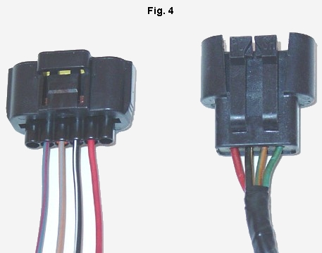
     If are using the new style 6 pin harness then you need to pay a little more attention to detail. The 6 pin harness isn’t color coded and there starts the confusion. Most people place the connectors next to each other and start from one side replacing one wire at a time, don’t do this. The wires for the old 4 pin run 1 through 4 starting on the left. The new 6 pin starts from the right 1 through 6. The wires at each end #1 and #6 are for the IAC. Wires 2 through 4 are used for the MAF. Take a look at Figures 2 and 3 to get an understanding of how they are positioned.

     The simplest way I can think of to show the proper install is using a table. Follow this table and you shouldn’t have any problems.

Old Style 4 Pin

New Style 6 Pin

Circuit Function


1 or E

IAT Signal Return

1 or A - 361 Red

2 or A

Vehicle Power (start/run)

2 or B - 969 Black/White

3 or B

Ground

3 or C - 968 Tan/Light Blue

4 or C

MAF Signal Return

4 or D - 967 Light Blue/Red

5 or D

MAF Signal, Input to EEC


6 or F

IAT Input

     Solder all your wires and place heat shrink over them to keep the moisture out.

     If you want to utilize the integral IAT sensor you can simply cut the connector off the current one on your vehicle, extend the wires and follow the table for the 6 pin for the factory wire placement. The sensor works off of resistance so you it doesn’t matter if you get these two wires switched around, it will still work.


More Tech Soon...
SCT Certified Home | Image Gallery | Links | Policies | Contact Us | About Us |
© Copyright 2004/2005, AcydLabs, Blue Oval Chips. All Rights Reserved. Website by AcydLabs
Valid CSS!Valid XHTML 1.0!